Time for another update

Many might think that the Mystery Amp thread from a design perspective ended when the web page went online a couple weeks ago:
https://www.decware.com/newsite/MYSTERY.htmlBut that's actually not true... With orders placed but no amplifiers built yet there was plenty of time to second guess yourself. It's the most difficult test you'll ever have to pass as it continually challenges your subjective likes and dislikes. Fortunately I do OK in that department because I explicitly trust my ears. And I'm happy to report there is nothing I would want to change about the way the amp sounds.
Sound, is however only part of the game. Usability, reliability, ease to build... etc. Even though I have the first Mystery Amp as the build sample and it has one of my best layouts ever... it can still be improved. You want everything to be easy to copy since we'll be building a lot of them. So in that light I began to see a new layout. The more I stared at the original layout, the more new layout appeared.
Keep in mind, the differences are subtle but just enough to tip the scale towards perfection - the obvious goal. It looks slightly cleaner because it is, and will therefor be slightly easier to build.
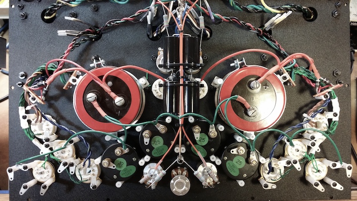
Amps are built in three stages. The first is assembling the chassis and all the parts that go on it. The second (shown above) is called the base layout. It consists of all the main power and ground paths and basically makes up a completed and working power supply. The third is adding components on the tube sockets to create the audio circuit.
While I was at it I also spent a great deal of time wrestling with what to do about the bias circuit. I spent so much time (days) getting the original to work the way I wanted it to, and now I'm second guessing it. Compared to the vast majority of bias circuits I really felt it was a masterpiece of form and function. It however shared a potentially fatal flaw just like most bias circuits that place the potentiometer in series with the bias voltage. If the tube draws excessive amounts of grid current it's possible the rating of the potentiometer can be exceeded and cause it to open (fail). That would remove the negative bias voltage from the grid and let your tube self destruct in a matter of minutes. While the chances of this happening are only 1 in 1000, I plan to make 1000 of these amps.
So with this in mind, I had to redesign the bias supply from scratch so that the potentiometers were only used to pull voltage to ground for both the supply and the balance. Sounds simple but it actually wasn't. Nevertheless, now it will be impossible for the condition of the pot or failure of a pot to kill the negative bias voltage. Instead, it will just let the negative voltage go to max which is enough to completely shut off both tubes at the same time... and that's a big improvement over letting the voltage go to zero since doing so causing the tubes to draw the full current of the power transformer until they melt or the transformer melts or the fuse blows, whichever comes first.
Anyway, a glimpse into the design process continues...
The amp pictured above is on my bench and nearing completion to become the new sample that everyone will use to build from. We're going to start building the first production units directly after the holidays.
I can hardly wait to see how well this amp is received. I'm committed to it. Even if everyone hated it, we'd do whatever it took to make it great. I don' think anyone's going to hate it though.
Enjoy the holidays... time to do some listening.


 Pages:


