|
A
do-it-yourself design
An affordable pair of speakers that demonstrate great frequency balance.
MODEL 103b Specifications: 28Hz ~ 22KHz ~ 8 ohms ~ 50 watts ~ 89.9 dB 1w/1m Type: Single Reflex 10 inch 3-way bookshelf full range These speakers have an unusually fabulous frequency balance with a warm full sound that is fast and accurate. Compared to other box speakers, you'll find the bass detail and balance to be among the best there is in this category of design. I've decided to offer the detailed plans along with parts suppliers so that you can buy everything direct and install the drivers yourself. This will not only save you money but will give you the satisfaction of owning something you made yourself. All of the drivers have been selected based on projected availability over the next two years, and of course cost. You can build these speakers yourself for around $500.00 for the pair. The cabinets are pre-built and the real oak veneer is ready for your favorite finish. If you're not much of a handy person, don't worry, just a little linseed oil hand rubbed into the cabinet yields a wonderful looking result. You might notice the $500. price. Building a pair of speakers that don't need a subwoofer and could work with a pair of Zen amps for the $500 price was a real challenge. Especially when you consider the fidelity of the Zen amp and it's imaging potential. Nevertheless, I feel I pulled it off, hitting the magic price by offering plans and letting you buy the components and cabinets wholesale direct. Everything comes from MCM Electronics, even the oak cabinets, so procuring the parts is very easy. None of the drivers are considered super high quality like the famous audiophile drivers you've come to know, but they have the correct signatures, and we show you how to tweak them into much higher quality - you'll love that part. I designed these speakers exactly how I design any speaker, and unfortunately I've come into a little frustration trying to communicate this technique to the average math guy who for some reason seems to be in the majority of D.I.Y. speaker builders that call me for advise. "How to design a speaker" - by Steve Deckert 2/2000 If you've read the article above then you understand my technique and what NOT to do. With that information, we can continue with some design process tips for this speaker project. The following D.I.Y. speaker project contains these 5 steps. We've already done the hardest one for you, Step 1.
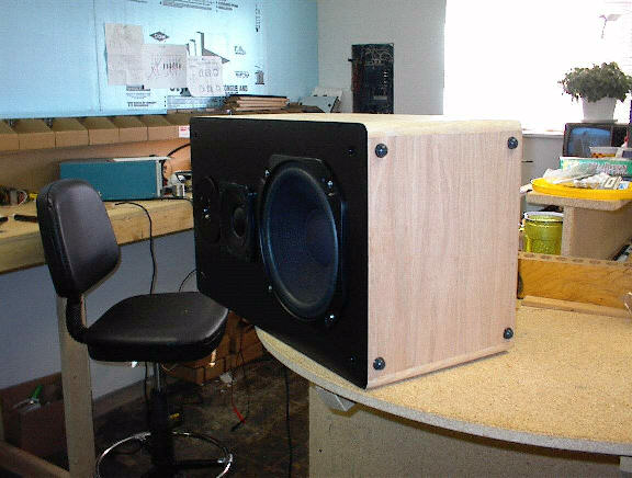
Selecting drivers and cabinets Selecting the drivers and cabinets has already been done for you, as this is a pre-designed speaker project. The drivers and cabinets were chosen based on availability, cost, and performance potential. This alone was the reason for choosing a three-way design over a two-way design. In the past I have always favored two-way designs for their simplicity and transparency. However, this being my first three-way design attempt I can now see that using my technique for speaker design works across the board and that if done right it is possible to get seamless results from a multi-way speaker. The good news being that these high quality oak real wood cabinets are pre-built and come with nice grills.
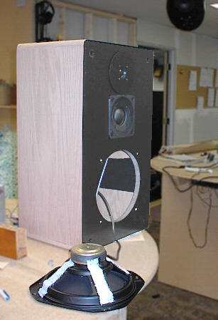
Tweaking the drivers and cabinets During the process of identifying the signatures of all three drivers and using the B&K to sweep the extremes of each ones response, there are some specific tweaks that must be done to all three drivers and the cabinets. The woofer was selected for the type of pulp in it's cone, the compliance of the suspension and the small one inch voice coil. These features combine to become a very fast well damped drive unit that will work in either a sealed or ported cabinet. However, being a mass production item, it uses a stamped steel basket which must be dampened. The picture at the top of this page shows strips of self-adhesive damping mat applied to the frame of the woofer. This eliminates the ring from the frame and consequently the ring from it's signature. Click here for a large picture of the woofer with the damping applied. The midrange was selected as perhaps the highest quality or most expensive of the three units because midrange in any speaker is the determining factor of how musical the speaker will be. This particular one, with a sealed cup on the back must be highly damped on both the sides and back with at least two or more layers of the same self-adhesive damping mat. Click here for a large picture of the midrange with the damping applied. The tweeter being of good quality is just fine the way it is. No real tweaking needs to be done to at. Click here for a large picture of the tweeter with hookup wire soldered in place. The cabinet is good quality and needs no major bracing, in fact because the target design for this speaker is lower power amplifiers adding additional bracing does very little. The hard surfaces of the interior however do need to be addressed. Because of the natural resonance's of this particular shape cabinet, I am counting on a certain amount of panel flex to add warmth to the overall signature. The interior is softened and slightly damped with the same self-adhesive material on all six sides. Pieces should be cut to cover the centers of each area, so that when you're done approximately 50% of the interior is covered. Click here for a large picture of the inside of the cabinet with damping applied. Additional things can be done to the cabinet to improve the sound of this project. In the prototype I did not implement these things to see what type of results you would have should you not have the resources to accomplish them. The results were poor, so I came up with a way to cheat by using a large piece of foam specially cut and adhered to the baffle. While this works, it prevents the use of grills, and is less than attractive. Click here to see the foam installed on the speakers. Notice that it is a 12" x 12" acoustic foam tile cut in half with a 2 inch hole in the center. It is installed directly on the midrange with the hole centered over the dome. Alternately, you could cover the entire face of the speaker baffle with either cork, or felt, or even velour of some type. If you did this you could get by without the foam. Also, if you wanted to really fine tune the response of this speaker, you could flush mount the midrange and tweeter by using a router to recess the openings. This will flatten response. A way to cheat and accomplish a similar result along with the previous modification is to install a 1/4 to 3/8 inch thick layer of soft gray foam over the entire baffle. This way when you surface mount your tweeter and midrange drivers, they will compress the foam and become recessed. This would be the best option of all.
Building and installing the crossovers The crossover, as always, is the dominant key to success in most speaker designs. In the case of this one nothing could be closer to the truth. The crossover must be wired exactly as shown, and if you won't the best possible results, the actual brand and type of caps and coils must also be duplicated. The schematic and parts lists are combined and available in our secure online catalog. If you absolutely can't build your own, i.e.. can't solder, you can purchase the crossovers already assembled from our catalog. (Note: these will be hand built to order so a 1 week lead time is needed before we can ship your order). We also can sell the parts if you want to do your own soldering. These are also available in our online catalog. Click here for a large picture of the crossover component layout. Click here for a large picture of the crossover shown after being soldered together. And finally, click here for a large picture of the crossover glued into the cabinet. Notice the entire unit was done without fancy boards or fasteners. Just some cardboard and some epoxy are all that is used.
This has been basically covered, except for a few quick tips. Always use a soft, yet firm gasket material between the cabinet and speaker frame. This applies to all three drivers. Never let the frame touch the cabinet. Make sure all drivers are installed with an air tight seal, no exceptions. Make sure all wiring is soldered to the drivers, do not use crimp connectors or spade connectors. Also make sure that wires are not left to hang down and touch the back of the woofer cone, or vibrate against the cabinet walls. The cutout for the tweeter will have to be notched a little to accommodate the wiring terminals. Drywall screws make the best fasteners for these type of drivers, unless you want to go to the trouble to installed threaded inserts. If you plan to use the grills, you will have to make a very small notch in the tops of each one to accommodate the oversize tweeter baffle.
Never assume you know what type of stand will be best for a given speaker. If you plan to use these speakers on stands set up for audiophile soundstaging and etc., you should use the following technique to determine the type of stands. The mystery is not only stand height and angle for best imaging in YOUR room, but also the way it couples to the speaker and the floor. We use stick on rubber bumpers to de-couple the cabinet from its stand ensuring warmth in the presentation. However, you may find spiking your stands is better. I have had several situations where the stands have ruined the sound of speakers. The way to choose a stand is to first find the correct height and then angle for the best imaging. Do this by using whatever you can find to set the speakers on until you think you have it. Then buy some stands that height. Make sure spikes are removable so that you can experiment with them.
As for listening to the speakers, you should have no problem doing lots of that, and if you think the speakers sound bad, get two of our Zen Triode amplifiers and prepare to be shocked. Cheers,
Steve Deckert
A COMPLETE PARTS LIST WITH PART NUMBERS AND ORDERING INFORMATION CAN BE VIEWED ON LINE ALONG WITH THE CROSSOVER SCHEMATIC IF YOU HAVE A SITE PASSWORD. (Also known as a Redemption number) If you need a redemption number click here parts listing - zspkrlist.pdf crossover schematic - zenspkr.pdf
|

