|
The CHRISTMAS COMES EARLY MOD Oct 2009 In
Part I we introduced the Christmas comes early mod (aka CCE mod)
but didn't get into specifics about what is actually
happening inside the tube to create this most apparent sonic
improvement. The mod improves clarity, dynamics and seems to show a
significant removal of typical edginess or grain in the sound.
This paper will show what is known so far and hopefully further
perpetuate the discussions going on in various amp building forums
around the Internet. AMPS For
starters it should be understood what context this mod is having this
result in. The context is Decware amplifiers, put simply, and
therefor this mod may not apply to or even be wise to implement in
other amplifiers. TUBES As
mentioned in part one, this mod is only applicable on tubes where the
suppressor grid is not internally connected to the cathode. The
EL34 tube as well as the SV83 are both examples of this
type of tube and are the two main output tubes that all
Decware amplifiers have been based on since the original Zen Triode amp
in 1996. THEORY As
predicted some basic measurements don't seem to show an effect or
explain the resulting improvement in clarity. This is why in the
interest of the greater good I have been inviting discussion on the
topic and writing these papers. If
we look at a triode with respect to the electrons that become dislodged
from the positively charged plate and have nowhere to go but back to
the plate we have to ask the following question: When the stray
electrons re-attached themselves to the plate where was their new
location with respect to where they left? It's unlikely they
bounced back to fill the same location they occupied before they were
dissloged. And why would this even matter? In a
pentode where the suppressor grid is kept at the same negative DC
voltage as the cathode, the dissloged electrons are also pushed back to
some location on the plate before they hit the screen grid and cause
problems with that. My focus is on the dislodged electrons coming
off the plate and being pushed back to the plate which is happening in
both the directly heated triodes and pentodes. I
can see the path in a large bottle triode that the dislodged electrons
take before they return to the plate could be a longer path than a
pentode where the suppressor grid greatly reduces the gap from the
plate. You might think that if this makes any difference at all,
pentodes would sound better than triodes, especially if they are triode
wired, but they usually don't. Again supporting the assumption
that the distance the secondary electrons travel back to the plate and
where they land on the plate is inconsequential. However,
the way I'm looking at it is that the mere fact there are secondary
electrons that have to be dealt with is a less than ideal thing. Due
to the fact that the suppressor grid deals with the dissloged electrons
from the plate, and that modifying it's operation changes the sound in
the way it does leads one to believe that the amount of or behavior of
the dissloged electrons have changed. Because
the change is for the better, you can only assume that dissloged
electrons are probably a bad thing for clarity and dimensionality. I've
listened to a fair numbers of triodes and triode wired EL34's over the
past 20 years and each has it's strengths. The triode is not
categorically superior to the triode wired EL34 as some would
think. However when the suppressor grid of the EL34 is modified
with the cap there is a huge difference in the presentation of the
amplifier for the better, despite the fact that typical measurements
show no substantial change has occurred. I think one of two
events are taking place: A) the phase angle of the AC component
on the suppressor is modified resulting in a deceleration of the
electrons as they pass through this sparsely wound
suppressor grid on their way to the plate resulting in less dislodged
electrons in the first place. B) the electrons that are being
dislodged from the plate are being absorbed by the suppressor
grid. In case A, there are less electrons being dislodged from
the plate so there are less secondary electrons being re-assembled on
the plate. In case B, there are the same amount of electrons
being dislodged from the plate, but less secondary electrons being
re-assembled on the plate, giving us the same result as case A.
TOPOLOGY Decware
amplifiers are self biasing designs that use a cathode
resistor that is often bypassed with a cap .
For the purpose of this article we will focus on one particular
single ended triode design that uses a triode wired EL34. This is
the amp that this mod was discovered on, so it seems a fitting place to
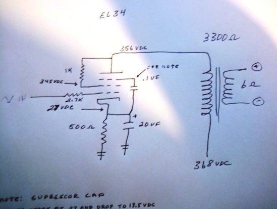
start. Below
is the output stage of this amp (or model SE34I.2)
MEASUREMENTS Below is an approx 1 volt signal on the
control grid at various frequencies in a working amplifier with an 8
ohm loudspeaker connected to it's output and set to a normal listening
level (about 1/2 watt). The chart below shows what the
suppressor grid (G3) is doing at different frequencies with and without
the 20uf cathode bypass cap installed on the cathode resistor.
Also in 3 locations starting at 200Hz the 0.1uf cap was jumped out with
a wire, effectively removing the CCE mod from the circuit. Also
notice that in this frequency bandwidth the DC voltage between the
suppressor Grid G3 and ground is not only there, but steady throughout
the spectrum.
It would be hard to interpret much
meaningful data from looking at the voltages, in fact when compared to
a piece of wire there is little difference made by the suppressor cap. I also did some other measurements
comparing the cap to a piece of wire in this same amplifier:
Again, everything actually improved slightly except IMD which got worse, however these values are so close they become pretty much meaningless with respect to understanding how the CCE mod makes the tube sound better. You'd almost have to capture it in real time reacting to the sudden dynamics of music vs. a simple AC sign wave if any of this data is to become meaningful. The kind of things I would like to see in a series of real time snapshots are beyond my resources and knowledge to actually measure so naturally no way to prove my theory. I came to the theory by process of elimination and driven by the fact that my ears are telling me something profound is happening even though I can't find it. I'll follow the discussions on various forums around the Internet regarding the CCE mod or Hazen Grid Mod as it's also called, with great interest. -Steve Deckert
From the RCA transmitting tube manual on air-cooled tubes from 1938: In all radio tubes. electrons striking a positive electrode may, if moving at sufficient speed, dislodge or "splash out" other or secondary electrons. In diodes and triodes, such secondary electrons produced at the plate usually do not cause any trouble because no positive electrode other than the plate itself is present to attract them. These electrons, therefore, are eventually drawn back to the plate. In tetrodes, the screen (operating at a positive potential) offers a strong attraction to secondary electrons when the plate voltage swings lower than the screen voltage. This effect limits the permissible plate swing for tetrodes because the major portion of the space current then goes to the screen rather than to the plate. The plate swing limitation can be substantially removed when a fifth electrode, known as the suppressor, is placed in the tube between the screen and the plate. Such five-electrode types are called pentodes. The suppressor in a pentode is usually connected to the cathode, or to a low positive or negative voltage, depending on the tube application. Because of its negative potential (in any case) with respect to the plate, the suppressor retards the flight of secondary electrons and diverts them back to the plate, where they cause no undesirable effects. Thus, in pentodes, the plate voltage may swing below the screen voltage." |
||||||||||||||||||||||||||||||||||||||||||||||||||||||||||||||||||||||||||||||||||||||||||||||||||||||||||||||||||||||||
|
Decware is a trademark of High Fidelity
Engineering Co. |