WICKED
ONE PLANS
Congratulations! You're IN! Here are the Plans...
And it was free this time!
The best way to let someone know you have
quality products is give them one.
All the plans on this site are of equal quality.
REMINDER:
This design is intended for experienced
box builders only.
...You're probably wondering what the magic angles are, and
all the dimensions etc. Okay, here they are: 8", 4", and 2". These are
the three magic numbers needed to layout this design, regardless of the
optional size you choose to make it. Wait a minute, optional size? Yes,
you have the option of making the length any
size between 24" and 36" ! The formula that determines the layout will
automatically self adjust for any of the optional lengths you might choose
for your horn.

BELOW ARE IMAGES ILLUSTRATING HOW TO LAY OUT THIS ENCLOSURE
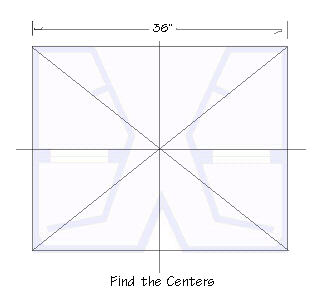
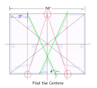
STEP ONE
Cut two panels 36" wide by whatever depth you want between 24" and
36". Lay one flat on your bench. The illustrations are a top view of the
panel laying on your bench. Take your tape measure and find the centers
as shown. Draw these lines on your panel.
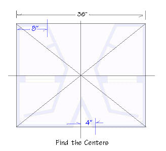
STEP TWO
From the bottom center measure 4" in each direction and make a mark
as illustrated in blue. From the top right and left edges measure 8" and
make a mark as shown. (only one side is marked in the illustration to keep
it from getting cluttered.) Remember whatever you do on one half you must
do to the other half. This is a mirrored design.
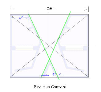
STEP THREE
Draw an X on the panel by connecting your marks as illustrated by the
green lines. As you can see, you now have the lines to lay out 10 panels
leaving only 4 to go!
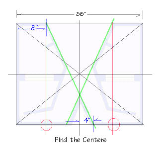
STEP FOUR
Starting at the top, draw a vertical line on each side of the panel
8" from the edge as illustrated in red.
STEP FIVE
Now draw two lines connecting the three points illustrated by the circles.
You now have the lines for two more panels, only two left now!
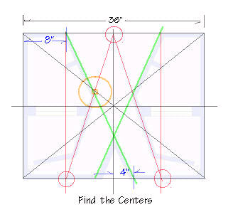
STEP SIX
Notice the intersection circled in orange. This point where two panels
join should land on the original black X you drew when finding the centers.
Following this point, like a road map, head North West on the black line
and turn North (up) on the red line then back to the starting point on
the green line. This triangle illustrates where to locate the stiffening
strut on the panel, and shows the correct width to make it.
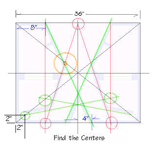
STEP SEVEN
Measuring 2" from the lower corner plot and intersection as shown.
This point determines the throat of the horn. Since
you're using material that is 3/4" of an inch thick, the throat opening
will be 1.25 x 1.25 inches when measured from the inside after the panels
are in place. NOTE: Enlarging this opening to no more than double, will
raise the high frequency cutoff point. Combined with reversing the speaker
baffle 180 degrees it is possible when using higher frequency drivers to
reach a cutoff of 5khz. This is desirable when using this design as a full
range enclosure. Applications of that would include PA use and Home theater
Center Channels. The green circles illustrate the last two intersections
needed to plot the line for the last panel illustrated by the green line.
CONSTRUCTION NOTES:
-
You now have the layout to build your horn. As you can see, the formula
will self adjust for any height between 24" and 36". Pretty neat huh..
This allows you to have some control over the physical size of the cabinet
for reasons of woofer selection, i.e.. internal chamber volume, and placement.
A direct parallel between the efficiency curve and the height dimension
is eminent. The larger up to the full 36 inches, will be louder.
-
The way to cut your panels that make up the rest of this horn is simply
to cut several 48 x 10" or 48 x 12" inch pieces to work with. The 10 or
12" dimension is used for 8 and 10" woofers respectively. Take one of these
stock panels and lay it on the large panel you just drew a crop circle
on. Using your pencil carefully align the panel with the lines you drew
and trace the other side so that you create a duplicate set of line 3/4's
of an inch away from the original set. This way you can see exactly how
your panels will intersect, and where to locate them.
-
Now take a protractor, and decide how you want to join your panels. You
may wish to end join them or miter them. The determining factor will be
the abilities of your table saw. I recommend drawing the joints on your
masterpiece too. That way you wont forget how you're planning to join each
panel.
-
You'll be pleased to find out there is a way to join the panels (end join)
so that almost every angle in the design can be cut from one setting on
your table saw. In other words, most of the angles in this design are identical,
no matter what size you picked for the height of the enclosure. If you
think this is getting rather amazing, wait until you hear the sound quality
of the perfectly flat, extended response of this horn and the incredible
efficiency!
-
The baffle for the speaker should be double thick, although it is only
a suggestion. Once you have cut it and placed it as shown in the illustrations
(Notice it follows the original center lines) you may flip it over 180
degrees if you want. Do what moves you as the best way. If you're going
for a full range response, it must be flipped.
-
Final construction tip... assemble the angled panels to the bottom that
you drew on with wood glue, and then hot glue the seams. This will hold
you box together during assembly, but before you do that, you might want
to transfer the design to the top, so that you can drill holes in the top
every 4 inches over every single panel in the box. We use a rubber gasket
glued to the top edge of all the panels to achieve a seal against the top.
The holes are for screws so that the top can be removed for service.
-
When selecting woofers for this enclosure, you can model a regular 4th
order single reflex box to determine the rear (sealed) chamber. If it wants
less air space than you have already built (gee you made the box first?)
simple add bracing to the sealed chamber until its internal volume matches
the requirement of your woofer. Do not adjust the baffle further back in
the chamber to reduce its size as a short cut, or you will increase the
Q of the box to well over 1.0 (boom boom)
That's it! One of the most complex but rewarding boxes you'll ever make.
I hope you appreciate the freebie, as these plans are compliments of myself,
Steve Deckert, to illustrate the killer designs sold on this site.
Naturally, although free, this information, and illustrations are copyright
(c) 1996 by High Fidelity Engineering Co. and represent a design which
is also copyrighted by High Fidelity Engineering Co. & Designer Steve
Deckert 1996. "The Wicked One" is a registered trademark of High Fidelity
Engineering Co. License is granted for the personal use of this information.
No permission is granted for commercial reproduction of this enclosure
design, including car audio road shops and installers for the intent of
wholesale or resale.
ONLINE
SUPPORT FORUM FOR THIS BOX
The DHM-108B is
the recommended woofer for this box
|